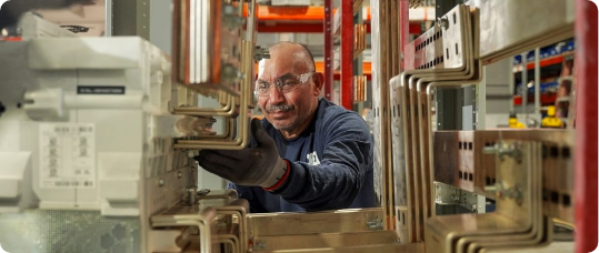
Copper bus bars are integral to switchgear and panelboards. Identifying the right copper bus bar that can take on carrying high current, surviving faults, and is reliable to keep the equipment running is important for consideration. What’s changing lately isn’t the fact that we use copper — it’s how carefully we’re optimizing it.
Between rising electrical loads (especially in data centers and industrial facilities), tighter temperature-rise limits, and real pressure to control costs and lead times, engineers are paying closer attention to copper bus design than they did even five or ten years ago. “Copper bus optimization” sounds like a niche topic, but it touches reliability, safety, efficiency, and manufacturability all at once. So what does optimization actually mean in practice, and what should engineers be thinking about?
The Ideal Copper Bus Optimization
The core job of a bus bar is simple: move current from point A to point B with minimal loss and acceptable temperature rise. But that “acceptable” part is where things get interesting.
As current goes up, heat goes up — and temperature rise is one of the most common limiters in switchgear performance. Bus bars heat from resistive losses and cool through convection and radiation, so geometry, spacing, and surface area matter just as much as material choice.
At the same time, copper prices have stayed volatile, and the industry is asking for smarter use of high-conductivity material without sacrificing performance. That’s the sweet spot optimization aims for: right-sized copper, not overbuilt, not marginal.
Real Time Considerations
Most people learn bus sizing as a current-density problem: pick a cross-section that carries the load. But real optimization goes further than that. Engineers now have to consider how the bus behaves thermally and mechanically in a real enclosure, not just on paper. Temperature rise limits, duty cycle, airflow, and the facility’s future expansion plans all factor into whether a bus is truly sized correctly.
Short-circuit events matter here too. During a fault, extremely high currents create strong electromagnetic forces that try to push phases apart or distort the bus structure. A bus that looks fine for steady-state loading can still fail mechanically if it isn’t braced and proportioned for fault conditions. That’s why more engineers are leaning on electro-thermal and mechanical modeling tools today — they help predict hot spots, confirm fault strength, and avoid overbuilding.
Details Matter
One of the most effective optimization moves isn’t changing material — it’s changing shape. For example, using multiple thinner bars in parallel can increase surface area and improve cooling compared to one thick bar, while still meeting fault requirements. Layout choices like phase-to-phase spacing and stacking order also affect electromagnetic forces during short-circuit events, which in turn impacts support design.
The takeaway: copper use can often be reduced without touching current capacity, as long as the thermal and mechanical system is engineered as a whole.
Better Joint Design Equals Quality Performance
The failure of bus bars is at joints. A joint with poor contact pressure or surface prep creates resistance, and resistance creates heat. That heating speeds up oxidation, weakens the connection, and can cause hardware to loosen over time — which raises resistance even more. It’s a quiet cycle, but it’s one of the most common ways temperature rise problems emerge inside switchgear.
Optimization at joints often comes down to being disciplined about the important details. Using correct hardware, following proper torque procedures, and preparing clean contact surfaces and consistently all make a big difference. In certain environments, plating choices like tin or silver also help stabilize the connection over the long term. In other words, a well-optimized bus system is rarely just about copper size; it’s about connection quality.
Determining the Right Materials: Copper or Aluminum
Copper still dominates in high-density, high-reliability environments because of its superior conductivity, ampacity, and mechanical strength. But optimization conversations often include hybrid approaches — for example, copper where space and heat margins are tight, and aluminum where weight or cost is the bigger lever.
Even copper-clad aluminum is showing up more in some applications, though engineers need to be realistic about terminations, galvanic compatibility, and performance expectations.
So the optimization mindset isn’t “use less copper at all costs.” It’s choosing the right conductor strategy for the system’s risk profile.
Manufacturing Constraints and Considerations
A design that’s theoretically perfect isn’t helpful if it’s hard to build consistently. Bus optimization today has to live in the real world of forming, plating, insulation, and assembly. Things like bend radii, tolerances across long lineups, and repeatability in switchgear manufacturing affect whether a design can be produced efficiently without quality drift.
When engineering and fabrication are aligned early, the result is a bus system that performs well electrically and flows smoothly through production. Optimization is seen at its highest, not just in copper usage, but in speed, consistency, and long-term reliability.
Copper and Optimization in Mind
Copper bus optimization is really about being intentional: using copper where it creates real electrical value, shaping and spacing it to manage heat, building joints that stay tight for decades, and designing with manufacturing reality in mind.
To learn more about DEI Power Solutions’ UL 891 certified switchgear and custom-built systems, please visit our website at https://deipowersolutions.com/ or give us a call at 866-773-8050.